Ahu Hot Watercoil With 3 Way Mixing Valve Piping Diagram Sol
Understanding the piping diagram for a 3-way control valve Method of statement for installation of compressed air piping system Air handling units
Chilled Water Air Handling Unit Diagram Schematic Diagram Of An Air
How does 3 way mixing valve work at lynn barton blog [diagram] venturi mixing valve diagram Solenoid valves valve ahu work example air
What is a pressure independent control valve?
Air handling unit diagram air handling unit ahu chilled water pipingChilled water schematics How solenoid valves workChilled hvac handling ahu pipe chiller.
Chilled water air handling unit diagram : modeling for hvac system3 2 valve schematic Steam to hot water heat exchanger piping diagramAir handling units.

Ahu chiller pipe piping
Condensing boilers and air handing unit (ahu): coil return temperatureAhu chilled water pipe connection and their works ! ahu valve, gauges [diagram] 3 way zone valve piping diagramChilled water piping schematic.
Chiller pipe connection detail for ahu[diagram] 3 way zone valve piping diagram How to install and use a 3-way mixing valve: piping diagram guide3 way valve piping diagram.

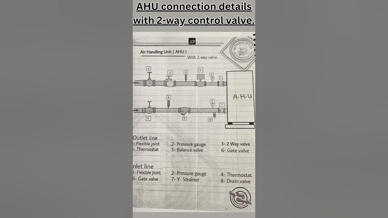
"optimizing hvac systems: ahu connection with 2-way control valve
Mixing valve diagramAhu chilled water piping connection details [dwg] Ahu chilled schematicMixing valve diagram.
Unit systems exhaust commercial ahu hvac air system types automation handling fan water vav cooling zone multi components glycol unitsAhu connection details with 2-way control valve. Ahu heating coil mixing unit design and commissioning with pibcv valveChilled water air handling unit diagram schematic diagram of an air.

3 way valve piping diagram
2-way 3-way on / off mixing modulating ahuHow to install and use a 3-way mixing valve: piping diagram guide Chilled piping water system chiller flushing air hvac pipeline compressed cleaning method chillers installation pipes insulation pressure fittings statement testingAir-cooled vs water-cooled chillers and how they work with air handling.
Ahu chilled water piping connection in autocad i hvac tutorial i hindi3-way diverting valve piping diagram .


![[DIAGRAM] 3 Way Zone Valve Piping Diagram - MYDIAGRAM.ONLINE](https://i2.wp.com/www.pmengineer.com/ext/resources/Issues/September-2014/Specific-Operating-Conditions/pme0914Siggy_Figure1_large.jpg)


